
This article explains how to resolve contact between triangular film and spherical contents together within one timestep in Newton. It covers the inputs, energy expressions, collision-processing order, and validation criteria needed for a port to another project. A 481-vertex bag experiment illustrates the resulting shapes and contacts.
Here, “Newton IPC” means a separate implementation tested in connection with Newton. The following describes experimental conditions and algorithms; implementation source and local libraries are not distributed. The public source for IPC principles is Li et al.’s paper and author resources.
Unfolding and tying a 30 µm bag
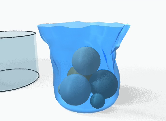
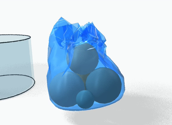
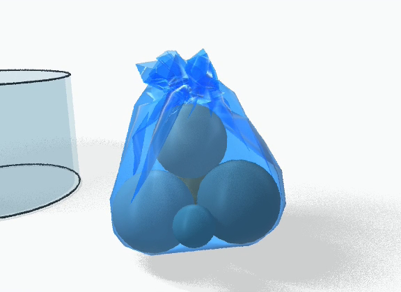
Differences from Newton VBD and suitability for plastic bags
As a bag opening is cinched, multiple layers of the same film slide against one another in a narrow neck. If two layers pass through each other even once, the fold order and the shape supporting the contents change after release. This IPC implementation checks separation during every move, making it useful for experiments that must track whether folded layers pass through each other. Rather than artificially increasing bending stiffness to support the shape, it allows bending computed from film thickness and interlayer contact to be configured separately. The same physical bending coefficient was applied to VBD.
| Comparison | Newton VBD experiment | Newton IPC in this article |
|---|---|---|
| Force transmission through the neck | Locally solves three position components per vertex in color-group order, passing updates to later groups and iterations. Same-color vertices run in parallel. This experiment used 48 iterations per substep. | Assembles membrane, bending, contact, and constraints into one global matrix. Each Newton direction includes the response of different layers and contents together. The current dense FP64 matrix increases memory and factorization cost as vertex count grows. |
| Self-contact and step limits | Vertex–face and edge–edge self-contact enabled, with 0.50 mm self-contact range and 1.50 mm extra search width. Conservative displacement limits (DAT) and a logarithmic barrier were also enabled for rigid–film contact. | Self-contact barriers use a 0.030 mm film-midsurface gap. Swept-motion candidates are found, and separation is checked for each Newton direction and after final FP32 rounding. Results that lose the gap are not recorded. |
| Contents and computation | Spheres are rigid bodies with mass and rotational degrees of freedom. Useful when the same framework must also handle more complex rigid bodies or joints. | Contents are translating particles with radius and mass. Film-layer and spherical-content separation can be checked. Experiments where nonspherical-body rotation and frictional torque matter require extending this model. |
The original VBD paper describes the per-vertex solve; Newton’s official solver documentation describes its self-contact and rigid-contact options. The settings above are from the project’s Newton 1.7.0 bag driver. Original Vertex Block Descent paper · Official Newton VBD documentation
Differences measured at the same instant
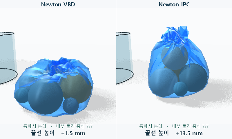
The comparison below is an earlier 8.45-second spreading-and-cinching experiment that both solvers completed. Both used the same 481-vertex mesh, 30 µm material properties, friction coefficient 0.35, seven spheres, and 3 cm cinching offset. Both released external support at 7.35 seconds. The video above is a separate experiment that supported the upper flap longer during cinching and ran until 10.50 seconds.
| Measurement from saved trajectories | Newton VBD | Newton IPC |
|---|---|---|
| Neck width x × y at 8.45 s | 31.04 × 32.04 mm | 38.45 × 42.01 mm |
| Upper-flap height at 8.45 s | 1.54 mm | 13.47 mm |
| Saved frames with detected self-intersection / total | 1,197 / 2,029 | 0 / 2,029 |
| Maximum sphere-center height range during final 1 s¹ | 23.76 mm | 0.80 mm |
¹ For each sphere, we calculated maximum minus minimum z, then took the largest of the seven values. Because this includes settling motion, it cannot establish the presence or absence of oscillation by itself. Self-intersection was checked on film surfaces saved every 1/240 second.
Under these conditions, IPC retained a taller flap and no self-intersection was detected in the checked frames. VBD actually had the narrower neck. Judging tie quality by neck width alone can therefore miss interlayer penetration. The runs share versions and baseline material properties, but VBD represents bin walls as box panels and IPC as fixed triangles. They also differ in spreading constraints, target lengths when tying stiffness is activated, contact settings, and damping. VBD uses an integration interval of 1/960 s; IPC starts at 1/240 s and subdivides on failure. These conditions jointly contribute to the observed differences.
1. Solver inputs and outputs
The experimental environment was Windows x64, Python 3.12.10, Newton 1.7.0, Warp 1.18.0, NumPy 2.5.4, PyTorch 2.11.0+cu128, and an RTX 5080. Length, mass, and time use m, kg, and s.
Model inputs. Prepare reference vertex positions, triangle connectivity, reference areas and dihedral angles, per-particle masses and fixed flags, material coefficients, and gravity. Assign a positive sphere radius only to independent sphere centers; film and fixed-obstacle vertices use zero.
Step inputs and outputs. The solver receives current positions and velocities, external forces, support targets, and tying conditions, and returns next positions and velocities. The 10.50-second video experiment has 2,520 steps. Including the initial state, film positions have shape 2,521 × 481 × 3, sphere centers 2,521 × 7 × 3, and triangle connectivity 928 × 3.
Inputs and outputs use different State objects. Positions and velocities use Newton’s FP32; distances, derivatives, and the global linear system use FP64; topology indices use int32. Inertia uses particle_mass and boundary conditions use particle_flags. External contact pairs and active triangle contraction are unsupported. Fixed obstacles are added as triangle surfaces with zero-mass vertices.
2. The problem solved in one timestep
The unknowns are all particles’ new positions x. For each free vertex, form the inertial target y = x₀ + dt·v₀ + dt²·(gravity + force/m). The objective is in joules and already includes 1/dt² in its inertial coefficient. Multiplying the other terms by dt² again would produce a different solve.
Φ(x) = Σ mᵢ ‖xᵢ − yᵢ‖² / (2 dt²)
     + E_membrane + E_bending + E_contact_barrier + E_friction + E_support + E_tie
Processing order within one timestep
- Compute inertial targets from current positions, velocities, external forces, and timestep; check initial geometry and contact gaps.
- Assemble gradients and approximate Hessians of membrane, bending, contact, and constraints. Solve a linear system with fixed degrees of freedom imposed to obtain the position-update direction.
- Find a displacement range preserving contact gaps, then reduce the step until energy decreases and update positions. Refresh contact candidates when the displacement range changes.
- Convert converged positions to storage precision and recheck gaps. Compute next velocities only from positions that pass.
This is an algorithm summary, not an executable example calling local solver functions or kernels.
For fixed degrees of freedom, zero the row and column, set the diagonal to 1, and the right-hand side to 0. Equilibrate with D = diag(H)⁻¹ᐟ², solve (D H D) z = −D∇Φ with GPU Cholesky, then recover Δx = D z. The convergence criterion is max(abs(Δx)), in meters.
Line search tests Φ(x+αΔx) ≤ Φ(x)+10⁻⁴ α ∇Φ·Δx up to 48 times. Exhausting line-search or nonlinear-iteration limits, or losing separation during rounding, discards that step’s output. The bag experiment retries from the same input with two half-steps, subdividing up to 7 levels. Invalid initial geometry or Cholesky factorization failure is reported to the caller.
3. Membrane, bending, and supports
Flatten each reference triangle into local 2D coordinates and form Dm with its two reference edges as columns. Newton’s tri_poses stores this reference transform’s inverse. If its rows are b₁,b₂, then B = [−b₁−b₂; b₁; b₂]. Stack the three current positions as columns of X and compute F=X B (3×2), C=FᵀF, ε=(C−I)/2, and log J=½ log det C. Reference faces must be nondegenerate with area A₀>0.
| Term | Element energy and implementation details |
|---|---|
| Neo-Hookean membrane | A₀ [μ (tr ε − log J) + λ (log J)²/2]. Explicitly selected for the bag path. Stress: S=μI+(λ log J−μ)C⁻¹. The geometric tangent uses S’s positive-eigenvalue part. Each triangle’s gradient and tangent accumulate into its three vertices’ global degrees of freedom. |
| StVK membrane | A₀ [μ ‖ε‖² + λ (tr ε)²/2]. The constructor’s default material, used for small CPU/GPU comparisons. |
| Interior hinge | ½ kθ wrap(θ−θ₀)². Index order: opposite vertex a, opposite vertex b, shared edge c, d. Face normals and c→d define the signed atan2 dihedral angle. wrap is atan2(sin, cos). Hessian: kθ ∇θ∇θᵀ. Negative boundary indices are excluded. |
| Physical coefficients | Plane-stress μ=Eh/[2(1+ν)], λ=Ehν/(1−ν²) are in N/m. For bending D=Eh³/[12(1−ν²)], let A be the combined area of the adjacent faces and ℓ the reference shared-edge length. The builder receives edge_ke=6Dℓ/A; the final energy coefficient is kθ=edge_ke·ℓ=6Dℓ²/A. |
| Temporary support and cinching | ½ kᵢ ‖xᵢ−targetᵢ‖² per selected vertex. Each supported material point has its own stiffness kᵢ (N/m). Remove the energy term when the hand releases. Hand geometry is unnecessary. |
| Maintaining the tie | Add ½·250·(‖xᵢ−xⱼ‖−Lᵢⱼ)² per material-point pair, with stiffness in N/m. Connections are only within and between the two bands, allowing the tie to translate and tilt. This differs from the model’s general springs or a frictional thread knot. |
4. Collision candidates, barriers, and friction
Each contact stores four vertex indices and weights w summing to zero. VT (vertex–triangle) uses (1,−b₀,−b₁,−b₂), EE (edge–edge) uses (1−s,s,t−1,−t), and sphere–sphere uses repeated indices (i,j,j,j) with (1,−1,0,0). Here b is the closest point’s triangle barycentric coordinate, and s and t are segment parameters. VT checks the triangle interior and three edges; EE checks endpoint combinations and interior closest points. Parallel edges are handled through endpoint–segment branches.
| Type | Candidate generation and exclusions | Offset c subtracted from distance |
|---|---|---|
| Film/obstacle VT/EE | Query vertex boxes against a triangle BVH and edge boxes against an edge BVH. Exclude a vertex belonging to the face and edges sharing a vertex. Record EE pairs in only one direction. | min_gap |
| Sphere center–face | Expand the VT vertex query box additionally by the sphere radius. Sphere centers are independent of film vertices. | R + min_gap/2 |
| Sphere–sphere | Add every unique pair of independent sphere centers. | Rᵢ + Rⱼ |
BVH boxes use per-axis minima and maxima over start and end positions. The query width includes dhat+min_gap; FP32 bounds expand outward by 4·eps32·(1+abs(coord)). If the candidate buffer is too small, reallocate above the actual count and query again. The candidate-reuse skin between iterations is 1.5 mm, separate from collision thickness.
r = Σ wᵢ xᵢ                 n = r / ‖r‖
g = ‖r‖ − c                  a = g − dhat
B(g)  = −k a² log(g/dhat)     if 0 < g < dhat
B′(g) = −k [2a log(g/dhat) + a²/g]
B″(g) = −k [2 log(g/dhat) + 4a/g − (a/g)²]
jᵢ = wᵢ n                    grad += B′ j,   H += B″ jjᵀ
At or above the activation distance, the barrier contributes zero; g≤0 lies outside the feasible domain. Because this uses distance in meters directly, substituting IPC derivatives for squared distance changes the forces. Barrier stiffness k is in N/m. Only positive normal-direction curvature is assembled.
Displacement bound. For each candidate, compute uᵢ=n·Δxᵢ. Approach is max(u₁,u₂,u₃)−u₀ for VT, max(u₂,u₃)−min(u₀,u₁) for EE, and u₁−u₀ for sphere–sphere. Over positive approaches, if the minimum g/approach is at most 1, start at 90% of that value; otherwise start at 1. Checking only both endpoints can miss penetration in between. This implementation uses a conservative displacement bound along the current separating normal.
Friction. For candidates active at step start, save load = μf·(−B′(g₀)) and w₀,n₀. For t=(I−n₀n₀ᵀ) Σw₀ᵢ(xᵢ−x₀ᵢ), add load·(sqrt(t·t+eps²)−eps), where eps=dt·0.001 m/s. New contacts within the step affect the barrier immediately; their friction loads update in the following step.
5. Bag experiment settings and comparison criteria
The bag is an open triangle surface with one central vertex and 15 rings of 32 points. The actual rim is vertices 449–480; the complete neck ring is 321–352 (zero-based, inclusive). Along each circumferential column, the four reference edges connecting corresponding points across five rings sum to 0.030 m. Vertex selection does not use folded world-space z differences.
| Setting | Value used in the handover example |
|---|---|
| Film | Thickness 30 µm, E=315 MPa, ν=0.45, density 925 kg/m³. add_cloth_mesh receives areal density 0.02775 kg/m². Built-in triangle and hinge damping: 0. Separate external force −12 s⁻¹·m·v applies only to film. |
| Environment and contents | Open bin 106 mm tall and floor: fixed triangles. Seven spheres: three of radius 26 mm, three of 12 mm, and one of 25 mm. Sphere mass: 250 kg/m³·4πR³/3. Cancel each sphere’s gravity until its scheduled drop. |
| Time and contact | dt=1/240 s, min_gap=0.030 mm, μf=0.35, k=1000 N/m, iteration limit 150. Default barrier activation distance: 1.0 mm. The saved full trajectory did not record activation, so do not infer and substitute another run’s 0.12 mm value. Position tolerance: 0.012 mm during manipulation, 0.0005 mm after release. |
| Spreading and cinching | 0–0.72 s: place over bin; 0.89–1.60 s: drops; at 2.00 s: lift two opposing rim points, remove from bin, and set on floor. 4.70–6.05 s: unfold upper flap. Check that all 32 columns unfold upward before proceeding. 6.05–7.10 s: gather; 7.40–8.40 s: support the flap while cinching selected vertices on two neck bands. |
| Tying and release | Apply internal tying at 8.40 s and shorten to target lengths by 8.75 s. Lower only the flap supports afterward, release external support at 9.40 s, and simulate until 10.50 s. The final target center for the five supports during flap lowering came from the post-release shape of the earlier spreading experiment. |
Final measurements from the existing complete task were neck width 38.83 × 37.20 mm and flap height 18.43 mm. Width is max−min of x and y over the 32 neck-ring points. Height is the median z of the 32 rim points minus the mean z of the neck ring. A 3.8 mm neck obtained from a different pre-shaped initial condition must not be used as this scene’s acceptance target. The existing trajectory also used stage restarts. Compare a fresh end-to-end run in a new environment by geometry, gaps, and preservation conditions.
6. Validation after porting and known scope
| Validation | Acceptance criteria |
|---|---|
| Small reference solves | 12 steps each for VT and EE scenes; midsurface distance >30 µm. Reject initial overlap and edge-through-face penetration; preserve output arrays on failure. Compare hinge-angle and assembled-energy gradients with central differences. |
| GPU comparison | Sample motion at 17 instants to check for missing reference candidates; check that α lies in (0,0.5) for fast crossing attempts. Over 6 steps in both scenes, GPU/reference position error for identical inputs ≤2×10⁻⁷ m; relative linear residual <10⁻⁷. This comparison uses StVK. |
| Bag integration | In two steps, check the GPU Neo-Hookean path, seven spheres, bin and floor, and output-array shapes. For the full experiment, check spreading geometry and post-release neck width and flap height. If vibration assessment is needed, separately measure each sphere center’s velocity and maximum displacement, and minimum film–sphere surface gap, over the final 1.10 s. |
Measurements from the reference implementation. CPU minimum midsurface distances were 838.96 µm for VT and 651.40 µm for EE; the bending angle changed from −14.036° to −7.229°. GPU crossing attempts were both limited to α=0.44775 and both scenes passed reference-position comparisons. The two-step bag result had film shape (3,481,3), sphere centers (3,7,3), and faces (928,3). Maximum coordinate-component differences from the existing trajectory’s first three frames were 0.0112 mm for film and 0 mm for sphere centers. The 10.50 s final values come from the existing full trajectory; the separate bag comparison covers only the initial two steps.
The current global matrix is dense FP64. For N total particles, one matrix alone occupies 8·(3N)² bytes; Cholesky typically costs O(N³). This example has 622 particles including fixed obstacles. When scaling to larger scenes, separately measure candidate counts, assembly time, and factorization time, while retaining the same small reference tests.
The supported scope is triangle surfaces and translating sphere particles in a single world. General rigid rotation, frictional torque, tetrahedra, multiple worlds, and bending on arbitrary nonmanifold meshes are outside the validated scope. Barriers sum per candidate, without area weighting or a special parallel-edge mollifier. Contact response can change with mesh resolution. These small tests alone do not guarantee no oscillation, no penetration under arbitrary conditions, or realistic plastic-film folds. See the authors’ resources for the original IPC method and scope. Li et al., Incremental Potential Contact, SIGGRAPH 2020