
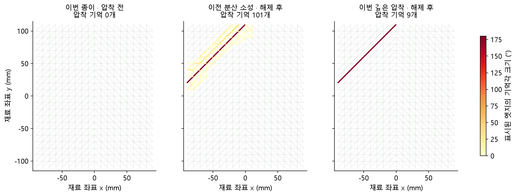
Grip a uniform sheet to form a rounded fold. Release the grip in proportion to how far the tool has actually pressed along the edge, and remember only the deeply pressed regions as creases. After removing both the tool and the grips, the sheet retains its fold while the upper panel remains straight.
November 11, 2026 · MuJoCo 4.0.0 CPU · Python 3.12.10 · Windows. The videos and measurements come from saved experimental records. Shared media retain their original Korean labels; the captions and descriptions below are in English.
176.93° · overall fold angle three seconds after full release
0.115 mm · upper-panel bulge at the same instant
0 / 25,216 · midsurface intersections in the inspected steps
The experiment combines MuJoCo’s Newton solver and discrete integration with an external material model, grip handoff based on measured reaction forces, and IPC retries of risky contact steps. Pre-run and post-run hashes matched for the engine source and 610 installed-package files. This physics run did not use Warp.
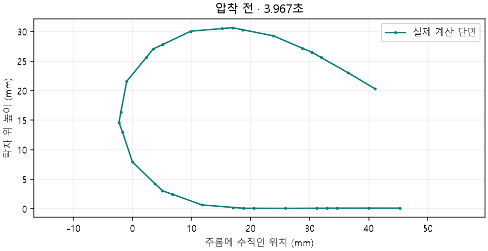
From a rounded fold before pressing to the released shape
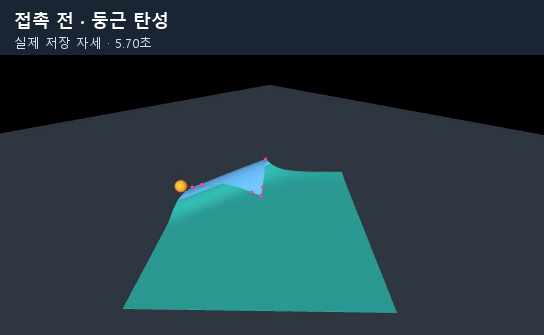
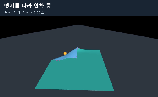
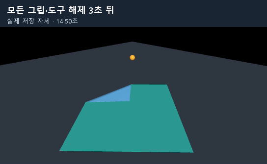
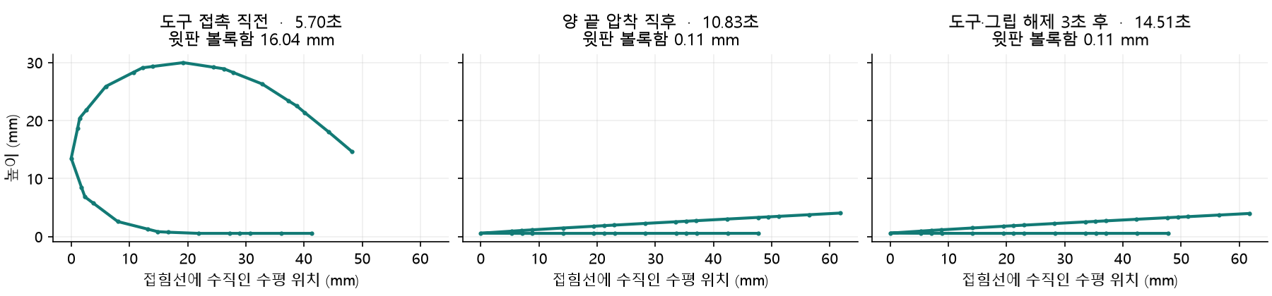
| Observation | Upper-panel bulge | Maximum cross-section height | Pressed memories |
|---|---|---|---|
| Just before tool contact · 5.70 s | 16.041 mm | 29.98 mm | 0 |
| Just after pressing both ends · 10.83 s | 0.109 mm | 4.05 mm | 9 |
| Three seconds after full release · 14.51 s | 0.115 mm | 3.98 mm | 9 |
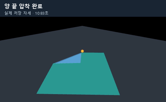
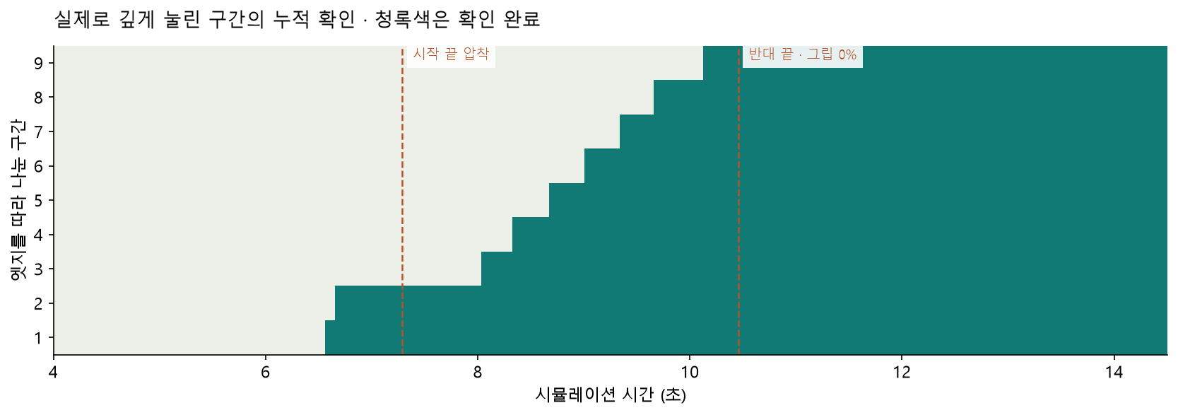
Both endpoints and all 9 intervening segments were pressed. After release, tool and grip forces are 0 N, and the change in remembered angles is 0°. The final positions and angles are actual integration results.
The VBD reference and the previous residual curvature
The following video shows an early cross-section experiment comparing material formulations. VBD and MuJoCo with an external material model produce similar rounded folds. This experiment uses a 240 × 240 mm sheet with a fixed base region and permits general plasticity without a pressing tool. Its conditions differ from the 180 × 220 mm pressing experiment described later.
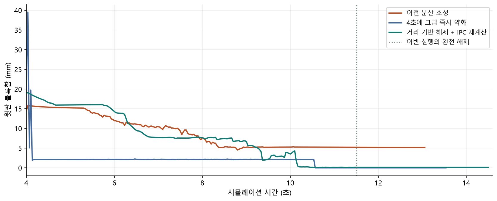
In the subsequent table-pressing experiment, the previous MuJoCo model retained a large upper-panel bulge. At the same upper-panel edge, the actual and remembered angles were approximately 0.14° and 0° for VBD, versus 27.90° and 28.45° for the previous MuJoCo model. The previous material had already remembered the bent upper panel as its reference state.
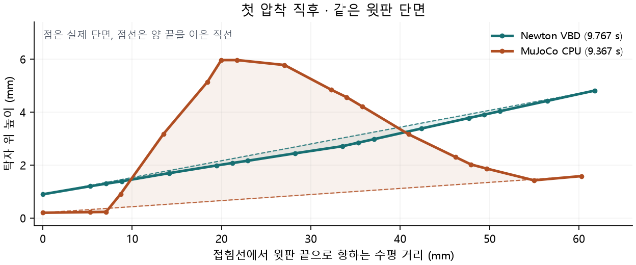
The current implementation gives every edge the same initial bending rigidity and keeps the reference angle at 0° in upper-panel regions unrelated to pressing. The material and grips were configured together for the uniform-paper requirement, rather than inheriting the VBD demo’s preset stiffness pattern and general plasticity.
VBD is an implicit method that updates vertex blocks sequentially and in parallel. The paper demo’s particular memory rules were defined in separate application code. Vertex Block Descent paper · Newton Physics 1.7 solver documentation
The pseudocode in this article explains the processing order; it is not executable reproduction code. Inputs are the triangle mesh’s current positions and velocities, edge lengths and areas, remembered angles, tool and table reaction forces, and grip state. Model construction and contact-search implementation details are omitted.
What the built-in Newton solver does, and the limits encountered
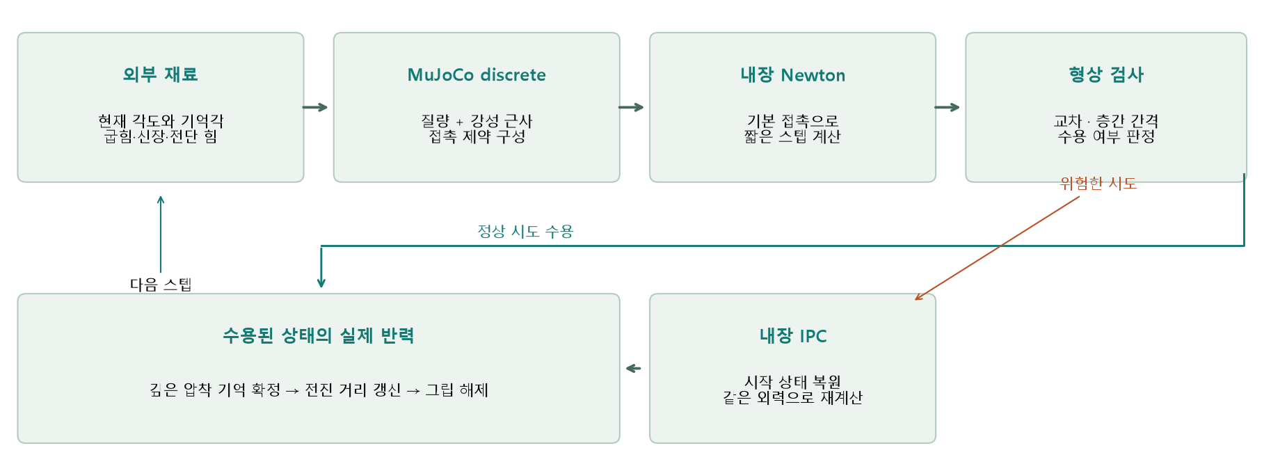
MuJoCo’s solver="Newton" selects the internal method for solving constraints. Discrete integration uses mass and an elastic stiffness approximation together with contact constraints. Material and control rules determine which angles the paper remembers and when the grips release.
| Constraint or observation | Identified cause | Change in this experiment |
|---|---|---|
| Built-in plastic reference-angle range | The inspected 4.0.0 2D shell plasticity code limits the local reference angle to ±1.3 rad, approximately ±74.5°. | Store external remembered angles and calculate elastic moments relative to them. |
| External forces versus internal stiffness | Not every derivative of a material formulation supplied through a force callback automatically enters Newton’s matrix. | Supply a stiffness approximation compatible with the flex coefficient structure. |
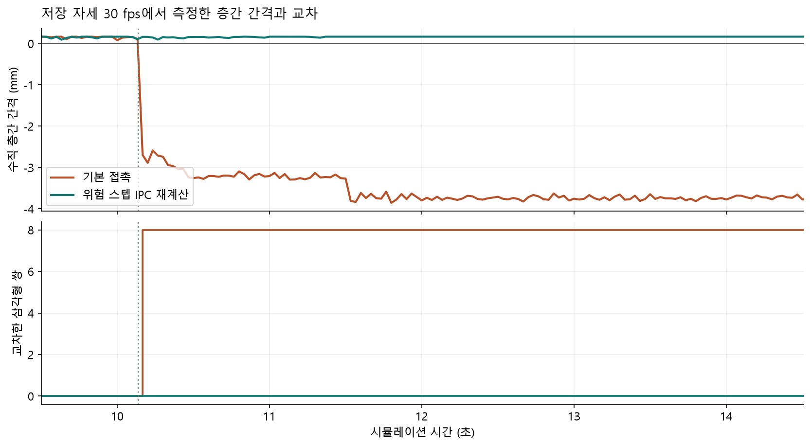
| Two thin layers passing through each other | The default discrete-contact control first detected intersections at 10.139 seconds. | Check gaps and intersections, then retry risky attempts with IPC. |
| Stalled IPC advancement | Earlier runs encountered incomplete-advance warnings and exhausted constraint memory. | Restore incomplete steps and retry with a shorter interval. Do not commit progress or memory on failure. |
| Residual upper-panel curvature and premature unfolding | These arose from the previous external memory rule and grip-weakening schedule. | Remember only deep pressing and release the grip according to supported forward travel. |
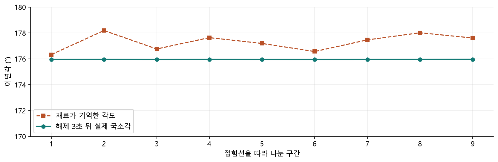
The built-in ±74.5° limit applies to one edge’s plastic reference angle. It is not a limit on the overall angle to which external forces can fold the sheet. The final median external remembered angle in this run is 177.46°.
Pseudocode · reference-angle limit observed in the built-in 2D shell
When elastic bending exceeds the yield criterion
    candidate reference angle ← current angle offset back by the yield range
    reference angle ← clamp candidate to −1.3 … +1.3 rad
    store plastic state in the engine's curvature representation
The public API documentation explains Newton’s constraint calculation and user force callbacks. MuJoCo Newton algorithm · Passive force callback
An elastic upper panel, with memory reserved for deep pressing
All remembered angles start at 0° in a fresh, flat sheet. Every interior edge uses the same bending rigidity, D = 0.0002 N·m. The difference between dihedral angle θ and remembered angle r produces the elastic moment.
k = 12 D L² / (2A₁ + 2A₂)
M = k · wrap(θ − r)
vertex bending force = −M · ∇θ
L is the edge length; A₁ and A₂ are the areas of its two adjacent triangles. Even with uniform D, angular stiffness k varies with mesh lengths and areas. In-plane forces use BW-family stretch and shear formulations. Here, wrap takes an angular difference into the principal interval, and ∇θ is the dihedral-angle gradient with respect to vertex positions.
Pseudocode · connecting external forces and a stiffness approximation
Initialize
    calculate target angular stiffness from each edge's length and areas
    set bending and in-plane stiffness approximations compatible with MuJoCo flex coefficients
    update the model's derived constants
    all external remembered angles ← 0

Passive force callback
    calculate bending, stretch, and shear forces from positions and remembered angles
    replace built-in spring and damper contributions on the paper's degrees of freedom
    add the calculated forces to the corresponding generalized forces
The stiffness approximation enters discrete integration’s effective matrix through the built-in flex structure. It still differs from the full nonlinear tangent stiffness that VBD updates at the current configuration during iteration. Matching external forces and matching the solver’s internal iterations therefore require separate examination.
Pseudocode · updating deep-press memory from an accepted physical state
supported contact ← tool aligned with the upper surface
                    and tool reaction > 0.01 N
                    and table reaction within 19 mm > 0.003 N

For each edge actually in contact
    current angle ← signed dihedral angle of the two current triangles
    deeper ← |current angle| > max(90°, |remembered angle|)
    same direction ← first record, or current and remembered angles have the same sign

    If supported contact and deeper and same direction
        remembered angle ← current angle
        pressed-memory flag ← true
The 90° threshold is the deep-press recording criterion for this experiment, not a universal yield angle measured from real paper. In a rounded fold, total rotation is spread across multiple edges. A large overall fold angle can coexist with individual edges that remain elastic relative to a flat reference.
Hold the grip, then release it according to pressed travel
Corner grips fold the sheet. During pressing, a finite-force grip holds 4 vertices on the upper sheet’s two free edges to maintain the elastic shape until tool contact. The free-edge servo has a per-axis stiffness of 800 N/m and a maximum force of 0.45 N.
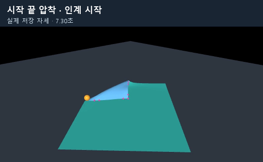
The spherical tool, with a radius of 6 mm, rises, aligns, and seats on the rounded lip. Once supported contact is established, the grip’s downward force ramps on over 0.2 seconds. The tool makes the first deep crease, rolls toward the starting endpoint, confirms that endpoint has been pressed, and advances toward the opposite end.
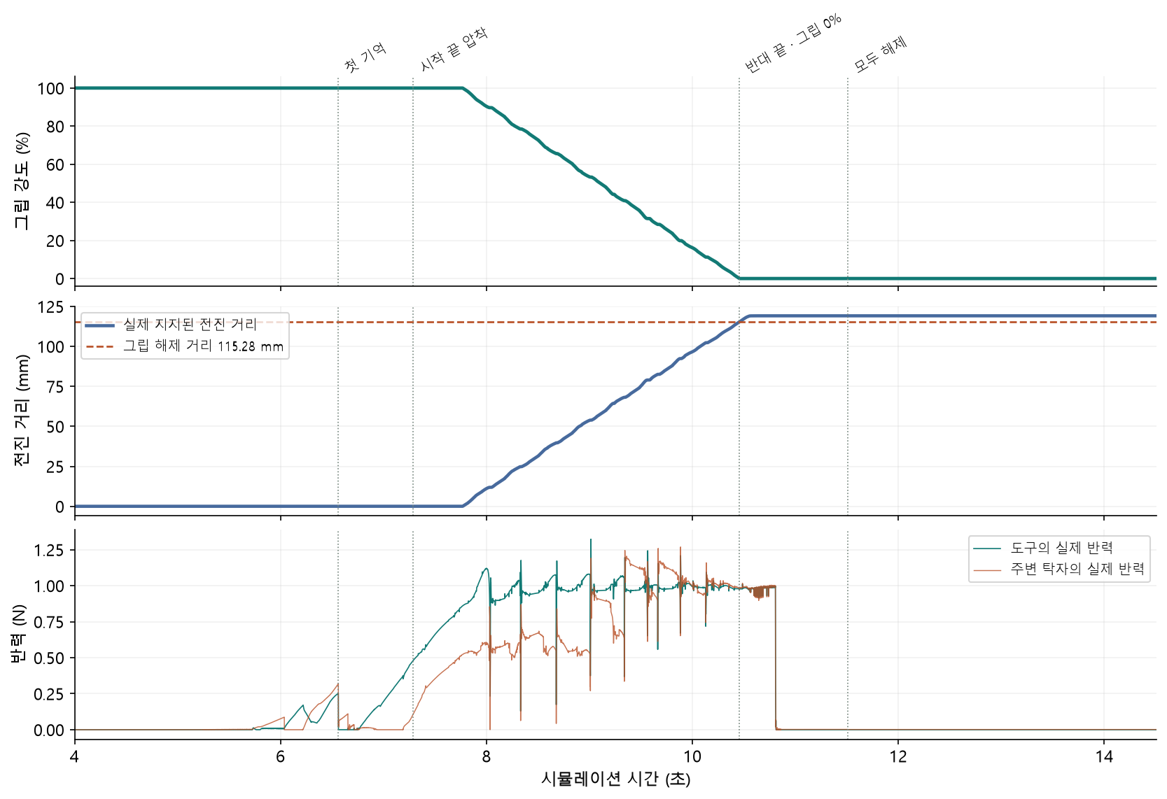
w = max(0, 1 − s / (L − 2R))L is the folded-edge length, 127.28 mm; R is the tool radius, 6 mm. Here s is the verified continuous forward distance after pressing the starting endpoint. Folding-side grip strength w reaches 0 after 115.28 mm of supported forward travel.
The target tool load is 1 N. During pressing, the difference between measured reaction and target load adjusts the tool’s commanded height. Forces and contact calculations determine the final shape of the paper’s interior vertices.
Pseudocode · grip handoff driven by actual contact-point advancement
Until the first deep crease and pressing of the starting endpoint are confirmed
    folding-side grip strength ← 100%

Then, whenever supported tool contact exists
    contact position ← longitudinal position relative to the sheet's current endpoints
    If it connects to the previous contact range within one tool diameter
        furthest pressed position ← max(previous value, current contact position)
    forward travel ← furthest pressed position − handoff starting position
    grip strength ← max(0, 1 − forward travel / 115.28 mm)

If both endpoints and all 9 segments are deeply pressed and grip strength is 0%
    finish pressing and lift the tool
    release base support and calculate the free response
Stopping, reversing, and moving through the air do not increase forward travel. Deep creasing and the presence of two layers under the tool are checked separately, so reaction force from pressing a single flat layer cannot count as success.
Detecting layer penetration and retrying the step
Even after successful grip handoff and deep creasing, the two layers could pass through each other. The control below uses the same material and the same pre-press state. On the left, default contact is calculated in two short steps. On the right, risky attempts are additionally retried with IPC.
During pressing and release, each external control interval of 1/1200 second contains two internal contact steps of 1/2400 second. Each attempt ends with checks for intersections between triangles that do not share vertices and the upper layer’s vertical gap. If the gap is smaller than ¼ of the collision radius, or an intersection exists, the simulation restores the preceding state and retries with IPC under the same external forces.
Pseudocode · default attempt and IPC retry
Save the state at the start of the short step
Advance a short step using default Newton contact

risk ← triangles without shared vertices intersect
        or upper-layer vertical gap < collision radius / 4

If risk
    restore the starting state
    advance a built-in IPC step with the same tool and grip commands

    If IPC warns of incomplete advancement
        restore integration state, contact multipliers, and contact history
        halve the time interval and retry
        if the retry limit is reached, record failure and stop without committing progress or memory

Read actual reaction forces from the accepted state
Update external memory and grip handoff
Append intersection checks to the validation record| Validation item | Default contact | IPC retry of risky steps |
|---|---|---|
| Short steps with detected intersections | 10,482 / 25,216 | 0 / 25,216 |
| Saved configurations with reversed layer order | 132 / 437 | 0 / 437 |
| Upper-panel bulge after release | 6.280 mm | 0.115 mm |
| Retained pressed memories | 9 | 9 |
| IPC retries of risky attempts | 0 | 2 |
The current run also uses a CPU thread pool, so this is not a single-variable comparison with an otherwise identical execution environment. The observed result is that this combination preserved both the crease and the layer order.
IPC contact multipliers and history are not fully preserved by saving the ordinary integration state alone. These arrays were saved separately for retries. Flex self-contact handled directly by IPC carries normal reactions; switching between default contact and IPC also introduces differences in contact friction handling.
The IPC used here is a contact mode of MuJoCo’s built-in discrete integrator. Official IPC support, state, and friction documentation
Does the crease survive release?
| Check after release | Result | Interpretation |
|---|---|---|
| Overall fold angle | 176.93° | The sheet retains its overall fold. |
| Median actual angle of the 9 crease edges | 175.95° | The pressed local crease remains. |
| Pressed memories outside the path | 0 | No pressed memory spreads over the broad upper panel. |
| Change in remembered angles after release | 0° | The stored material state persists after tool removal. |
| Tool and grip forces after release | 0 N each | Free response after removing external gripping forces. |
| Saved pressing configurations with the tool below the upper layer | 0 / 189 | Actual tool contact remains above the upper layer. |
The minimum logic to transfer to another project
The connections to implement are material calculation, manipulation control, and validation of accepted states. The following pseudocode summarizes the overall sequence using the built-in Newton solver.
Pseudocode · fold once, press, and fully release
Configure the model
    MuJoCo 4.0.0 CPU, Newton, discrete
    uniform 2D flex with vertex masses proportional to area
    moving tool and support, with force-limited grips
    connect external bending and in-plane forces and stiffness approximations
    initialize all external remembered angles to 0

Fold a fresh sheet using corner grips

During pressing
    find the rounded outer lip and upper surface on the current sheet
    adjust tool height from measured reaction forces
    maintain grips until the first crease and actual starting-endpoint press
    advance short physics steps; retry with IPC when risky
    update deep memory from contact in the accepted state
    decrease grip strength according to supported forward travel
    verify actual pressing at both endpoints and every segment

After pressing completes
    lift the tool and release all grips and base support
    continue the physics calculation for 3 seconds
validate fold angle, upper-panel bulge, memory change, and layer intersections| Validation condition | Value |
|---|---|
| Paper dimensions / grid spacing / material thickness | 180 × 220 mm / 10 mm / 0.20 mm |
| Areal density / uniform bending rigidity | 0.16 kg/m² / 0.0002 N·m |
| External control / pressing and release contact step | 1/1200 s / 1/2400 s |
| Tool radius / target load | 6 mm / 1 N |
| Travel required to release grip / recorded travel | 115.28 mm / 119.12 mm |
| Collision radius during pressing | Gradually increased from 0.10 mm to 0.25 mm |
| Computation time | Approximately 992 seconds from the saved folded state through pressing and release |
The current implementation assumes a single flex, 3 slide degrees of freedom per vertex, and the designated first diagonal. Other joint structures require converting vertex forces into generalized forces. Other meshes also require redefining the material locations of the path and grips.
Connecting an external force callback alone does not automatically transmit the stiffness approximation. Compatible terms must also be set in the model’s flex coefficients, followed by an update of derived constants. Force callbacks are global, so simultaneous simulation of multiple independent models requires model-specific dispatch and state management.
The public API scope is described in the official documentation. Solver and integrator settings · Scope of global callbacks
Physical and numerical scope of these results
Midsurface intersections were zero, but thickness clearance still contains error. The minimum vertical layer separation in saved configurations was 0.094 mm, smaller than the 0.20 mm material thickness. The engine recorded a maximum self-contact envelope overlap of 0.396 mm.
The minimum gap was measured by projecting the centers of inverted upper-layer triangles vertically onto the lower surface. A global minimum distance over every triangle pair was not measured. Intersection checks covered accepted short steps during pressing and release; they do not establish a guarantee for the entire continuous trajectory between every default step.
Validation covers one fold and press along the first diagonal, followed by 3 seconds after full release. Reverse folding, crease erasure, repeated fatigue, tearing, and fiber directionality require additional material rules and validation. The approximately 992 seconds of computation excludes initial folding and video rendering.
The comparison runs began pressing from the same state at 3.999 seconds, obtained by folding a fresh sheet. They shared its positions, velocities, and remembered angles. The graphs and additional videos were created from those saved records; the physics simulation was not rerun for this document revision or blog import.
Implementation and public-documentation versions
The experiment ran on MuJoCo 4.0.0 CPU and Python 3.12.10. The original experiment record identifies engine revision a937a4f916dc586660145973b015e56e04043377 as the basis for its inspection of the built-in 2D shell plasticity limit and IPC handling. Internal stiffness-array structures and experimental IPC behavior are version-dependent. The public latest documentation supports API interpretation; the measurements come from this experiment’s saved results.
Papers and public library documentation
The videos and graphs are records of the experiment. The following sources explain the algorithms and API background.
- Anka He Chen et al., Vertex Block Descent, SIGGRAPH 2024. Implicit physics through vertex-block updates. Paper
- MuJoCo’s Newton constraint calculation and the effective matrix of discrete integration. Computation
- MuJoCo solver settings and experimental IPC mode, including state, supported contacts, and friction scope. XML Reference
- MuJoCo user passive forces and global callbacks. API Globals
- VBD and solver configuration in Newton Physics 1.7.0. Solvers