
First define what the hardware sends, transfer that contract into simulation, then generate tactile values from contact. This article follows the path to 176 sensing points, three resultant components per finger, and force images.
Research and experiment record date: November 11, 2026. These are saved results supplied with the original document. The physics experiments were not rerun while preparing this blog post.
Scope. The original investigation examined official documentation and SDK examples, then analyzed the supplied hand_tactile.xml and conversion implementation. It did not collect raw packets or calibration data from physical hardware. Distinguish the official contract, current implementation, and information still missing.
01. What does the hardware send?
The subject is the fingertip-pad tactile interface of Wuji Hand 2.2. Wuji Technology manufactures the hand and provides its official interface. The reviewed public sources did not establish a separate module supplier, transduction principle, or physical full-scale range. We therefore do not identify it as a particular third-party, magnetic, or piezoresistive sensor. Check FingertipSensorInfo.model alongside the device specification; the model string may be empty. [1]
Hand 2 fingertip pads, the hand’s passive covering, and Wuji Glove tactile data are different subjects. This article addresses five fingertip streams. The official model is a rigid-body model with pad geometry, which alone does not simulate elastomer deformation or electrical sensor response. [2]
1.1 Metadata first, frames second
Do not assume the input is a fixed float[528] array. Decode each finger’s bytes using info.format, and verify the frame’s info_digest against the metadata. Refresh the decoder when metadata changes. [1]
| Information | Hardware fields | Meaning for simulation |
|---|---|---|
| Configuration | point_count, rate_hz | Point count and output rate |
| Payload | point_stride, point_fields, aggregate_stride, aggregate_fields | Separate point axes from the finger resultant |
| Numeric interpretation | Per-field type, offset, scale, unit | Distinguish N from normalized output |
| Spatial layout | positions, point_rpy, base_xyz, base_rpy | Measurement positions and point force axes |
| Resultant frame | aggregate_xyz, aggregate_rpy | Resultant axes and fixed application point |
| Synchronization | header, digest, info_digest | Time, sequence, and metadata consistency |
Field definitions come from the official contract [1] and decoder [3]. These explanatory expressions restate the contract:
Frame length = point_count × point_stride + aggregate_stride
Value = raw value decoded little-endian using type and offset × scale
The official decoder reads fields at their offsets within each point, then reads the resultant and temperature from a separate final region. A simple sum of point values need not equal the firmware resultant. Different axes require rotation first; internal aggregation and calibration must also be checked. [3]
1.2 Identical fx/fy/fz names can carry different units
| Channel | Official specification | Interpretation boundary |
|---|---|---|
| Point axes | 40 thumb points; 34 on each other finger; 176 total | Prioritize the device’s point_count |
| Point values before firmware v2.4.0 | Force in N | This does not establish physical measurement limits |
| Point values from v2.4.0 | Normal fz: 0…1; tangent fx/fy: −1…1 | Normalized against full scale, with saturation; 1 is not 1 N |
| Finger resultant | Three axes in N | Five fingers yield 15 values, separate from point normalization |
| Temperature and rate | °C; documented native 100 Hz | Distinguish arrival time from measurement time |
Counts, rate, and axes are documented in [1,3]; firmware-dependent units in [4,5]. Hand hardware “2.2” and firmware “v2.4.0” use different version schemes.
Converting normalized output to N requires missing information. scale converts a raw field to its declared unit. If that is normalized, axis-specific full-scale values or measured calibration functions are still needed. The simulation retains N without inventing those values.
02. Transfer hardware information into simulation
Transfer where, along which axes, in which units, and how frequently measurements are taken, not just appearance. These transforms apply once hardware metadata is available, unlike the synthetic point layout currently used:
R(rpy) = Rz(yaw) Ry(pitch) Rx(roll)
pᵢ(link) = R(base_rpy) pᵢ(module) + base_xyz
fᵢ(link) = R(base_rpy) R(point_rpy[i]) fᵢ(point)
F(link)  = R(base_rpy) R(aggregate_rpy) F(aggregate)
SDK positions use m and angles rad. Verify the fixed transform from tip_sensor_frame to the simulated distal frame. Treat partially provided mounting fields as invalid metadata instead of filling them arbitrarily. aggregate_xyz is the fixed geometric pad center, not a moving center of pressure or measured contact torque. [1] [3]
2.1 Transferred properties and remaining assumptions
| Item | Current implementation | Next step for hardware agreement |
|---|---|---|
| Hand and pad geometry | Official 2.1 right-hand body plus the outer 2.2 pad reference | Confirm revision and mounting transform |
| Point count | 40 + 34 × 4 = 176 | Confirm device counts |
| Coordinates and order | Synthetic surface samples and indices | Replace with actual positions and indices |
| Force frame | One fixed pad frame per finger | Map point and resultant axes separately |
| Output | Contact-based N; 176×3 / 5×3 | Add calibration, normalization, and saturation |
| Spatial/time response | Gaussian σ=1.5 mm; 100 Hz recording | Measure response width, delay, noise, and hysteresis |
This is contact-based virtual tactile output shaped like Wuji’s interface, not a replica of firmware or internal sensor mechanics. Official 2.2 CAD adds pad links; this implementation still uses a 2.1 body. [6]
2.2 Pad generation prepares measurement locations
According to the original README and build.py, area-weighted candidates on the outer +Y surface of the 2.2 STL were projected onto the 2.1 collision surface. Conditions were normal Y >0.2, position Y>0, and exclusion of a 1 mm proximal boundary. Farthest-point selection placed 40/34 points. Each has a normal and two orthogonal tangents. These are not measured internal hardware taxel coordinates.
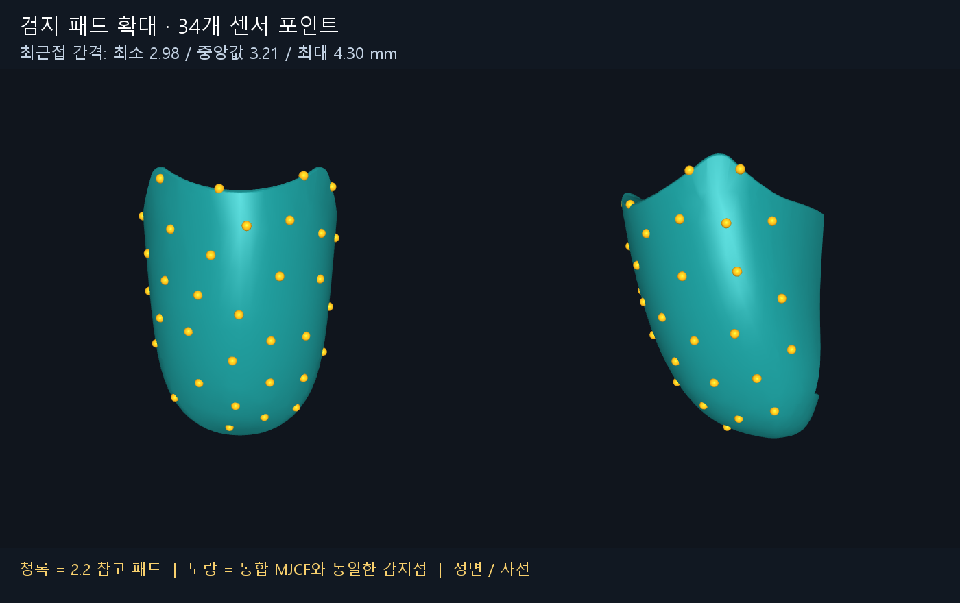
Sensor geoms add neither collision nor mass. Existing hand geoms handle collisions; the sensor mesh supplies measurement positions and directions. Yellow sites are markers. The original 20 joints and actuators, body mass, and inertia were retained. Force generation happens separately through the contact solution.
03. Generate tactile information in MuJoCo 4.0
The supported and validated engine is MuJoCo 4.0.0. This discussion follows its documentation, API, and recorded results. Earlier descriptions must not replace the meaning of native <tactile> in 4.0. mj_contactForce predates 4.0, but the sensor configuration, reading path, and validation here are scoped to 4.0.0.
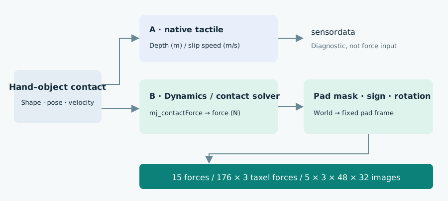
3.1 Native tactile output in 4.0
At N mesh vertices, <tactile> computes nonnegative penetration depth and absolute slip speed along two tangents. Output comprises [d₀…dₙ₋₁, |vₜ₁|₀…|vₜ₁|ₙ₋₁, |vₜ₂|₀…|vₜ₂|ₙ₋₁], not three-axis force or RGB. Tangential channels require three normal vectors per point: the normal and two tangents. [7]
For the index finger’s 34 points, the first 34 values are depth (m), the next 34 first-tangent speed (m/s), and the last 34 second-tangent speed (m/s). All are zero without contact. The expressions and procedures below explain principles; they are not executable reproduction code.
The implementation reads sensordata using sensor_adr and point counts. Five pads supply 528 values; the original six IMU values bring the model total to 534. Hardware 176×3 also contains 528 values, but physical quantities and layouts differ despite matching dimensions.
The engine gathers and deduplicates opposing geoms from contacts on the same weld body, then evaluates signed distance with each taxel transformed into the opposing geom’s frame. In the examined source, depth is maximum penetration across opponents; tangent speeds accumulate absolute components over penetrating opposing geoms. Do not assign arbitrary direction signs or interpret them as shear force. [8]
dᵢ = max(0, −signed_distance(pᵢ, opposing geometry))
No contact → dᵢ = 0, |vₜ₁|ᵢ = 0, |vₜ₂|ᵢ = 0
This describes one opposing geometry. depth × arbitrary stiffness is not the force rule used here.
3.2 Why mesh contact may produce zero native output
In 4.0, the opposing mesh needs an SDF octree prepared with needsdf before compilation. Otherwise native tactile skips it. Working physical collisions do not prove native sensing works. Primitives use analytical distances and SDF geoms use plugins. [7]
The sequence is: load the scene with MjSpec → enable needsdf on the opposing collision mesh → compile. Inputs are the prepared scene and opposing collision mesh; configuring only the sensor surface is insufficient.
The mesh-plate experiment in surface_contact.py uses this setting. The Foo Dog experiment instead uses resolved contact forces from its original 19 collision geoms, without native depth as input. Its mesh has no native SDF, so native depth and force images need not change together. Fine decorative detail can affect forces only to the extent represented by collision decomposition.
3.3 Extract forces from the contact solution
Given joint controls, pose, velocity, mass, inertia, gravity, friction, and contact settings, MuJoCo solves motion and constraints. Conceptually, this pipeline uses the constraint-force contribution below; the solution depends on contact model, solver, and time step. [9]
M(q) q̈ + c(q,q̇) = τ + J(q)ᵀ λ
                              ↑ contact and other constraint forces
mj_contactForce(model, data, contact_id, wrench) returns three force and three torque components in the contact frame. Only forces are used; the 15 outputs contain no torque. This API handles the constraint representation instead of slicing efc_force into arbitrary triples. [10]
Exclude contacts with efc_address < 0; one geom must belong to the relevant distal segment. For Foo Dog, the opponent must be among the object’s 19 collision shapes. Never count a record twice, while retaining distinct physical contacts on separate parts.
| Active-pad test | Condition |
|---|---|
| Front region | Distal-local Y > 0 |
| Near sensing points | Nearest synthetic taxel distance ≤ r |
| Direction | Outward contact normal · nearest taxel normal ≥ 0.25 |
| Radius | r = 0.9 × maximum nearest-neighbor spacing on the pad + 0.2 mm |
This approximate active-region mask needs real boundary and calibration validation. It excludes the distal back surface, inter-finger contacts, and support contacts from the object’s image without disabling those collisions.
3.4 Resolve signs and rotate into pad axes
Let G0=contact.geom[0] and G1=contact.geom[1]. Rows of contact.frame are contact basis vectors in world coordinates; its first normal points G0→G1. Rotate the returned force into world axes, then select the sign according to the pad’s side. [10] [11]
C = contact.frame.reshape(3, 3)
fᴡ(on G1) = Cᵀ fᶜ
fᴡ(pad)   = +fᴡ(on G1),  if the pad is G1
             −fᴡ(on G1),  if the pad is G0
With R the distal-to-world rotation, pad +x is distal +X, +y is distal +Z, and +z is distal −Y. This is the implementation’s convention, not every hardware taxel’s orientation.
A = [ 1  0  0 ]     # Columns: pad axes in distal coordinates
    [ 0  0 −1 ]
    [ 0  1  0 ]

fᴾ = Aᵀ Rᵀ fᴡ(pad)
Fᴾ_finger = Σ fᴾ_contact
Flatten [Fx,Fy,Fz] in thumb → index → middle → ring → pinky order for 15 values. Resultant magnitude is ‖Σf‖, not Σ‖f‖. Fingers have different orientations, so rotate into a shared world frame before summing whole-hand force.
Let n point from the pad toward the object. Estimate the pad surface from the contact midpoint as p_surface = contact.pos − n × contact.dist / 2, then transform it into distal-local coordinates for masking and distribution.
3.5 Distribute forces to 176 points and images
Solver contacts are not one-to-one hardware taxels. A custom spatial response model assigns their force to sensing locations. Gaussian weights around each contact are normalized to preserve all three resultant components.
rⱼ² = ‖pⱼ − p_contact‖²
Δⱼ  = rⱼ² − minₖ rₖ²
uⱼ  = exp(−Δⱼ / (2σ²)),  Δⱼ ≤ (3σ)²
      0,                  otherwise
wⱼ  = uⱼ / Σₖ uₖ           (σ = 1.5 mm)
fⱼ  += wⱼ f_contact
These equations express the recorded spatial response rule. Inputs are valid sample positions pⱼ, pad-surface contact position p_contact, and contact force f_contact rotated into the same pad axes. The cutoff uses relative squared distance after subtracting the minimum, not absolute distance 3σ. The nearest valid point therefore retains weight even for slightly off-surface contacts. Distance is local 3D Euclidean distance, not surface geodesic distance.
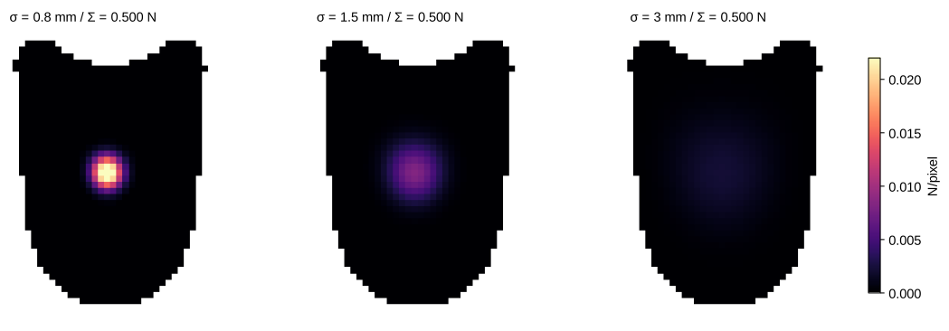
Apply this separately to 176 existing points and valid pixels of each 48×32 surface grid. Grids sample curved STL coordinates independently, rather than enlarging the 176-point output. Invalid regions are masked. Valid pixel counts are 1208 / 1111 / 1111 / 1111 / 1098.
Σ_pixel f_pixel = Σ_taxel f_taxel = F_finger (each of three axes)This preserves vector force sums, not moments after distribution, continuum pressure fields, or physical point readings. It is neither area-weighted integration nor FEM elasticity. Units are N/pixel; Pa requires additional surface-area and normal-component modeling.
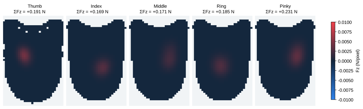
3.6 When to read: 1 ms physics and 100 Hz output
Metadata alone does not generate forces. Current-state collision detection and constraint computation must run. Native tactile is evaluated in the velocity stage, but these force outputs require the constraint solver. Updating position alone is insufficient. The demo takes ten 1 ms steps, calls mj_forward, then reads to align integrated pose, contacts, and forces. mj_forward does not advance time. [8] [10]
Inputs are the hand/object model, current state, joint targets, and 1 ms step:
- Update targets and advance physics with
mj_step, repeating ten times. - Refresh post-integration contacts and forces with
mj_forward. - Read valid contact forces, resolve signs and frames, and distribute to points and pixels.
- Record resultants and distributions with the simulation time.
This explanatory procedure includes no controller or private conversion-function source.
A 4.0 scheduling detail. The original XML uses interval=".01" without nsample, and compiled sensor_history is zero. The engine computes sensors directly in that case, so interval alone does not guarantee 100 Hz. Native rate limiting requires history storage. The force demo uses interval=0 and the reading loop above. [8] [12]
For separate native periodic updates, consider nsample="2" with interval=".01" on <tactile>, referencing an already-defined sensor geom and measurement mesh. This explains public 4.0.0 settings, not a complete executable scene.
Recording at 100 Hz means reading once per 10 ms, not modeling a physical low-pass filter or 10 ms integration average. Matching frequency does not match delay, bandwidth, or dropped frames.
3.7 Version-specific meanings
| Point | MuJoCo 4.0.0 meaning | Incorrect interpretation |
|---|---|---|
| Native tactile | Depth (m), two absolute tangent speeds (m/s) | Reading channels as Fx/Fy/Fz |
| Earlier descriptions | Do not apply 3.3.5’s penetration-pressure description to 4.0 [13] | Applying the older nonlinear interpretation to depth |
| Sensor/collision surfaces | Same-weld-body contacts activate a non-colliding sensor geom | Duplicating contact by enabling sensor collisions |
| Opposing mesh distance | needsdf in MjSpec before compilation | Assuming a visible mesh automatically yields native data |
| Native period | Check interval and nsample | Inferring 100 Hz from .01 alone |
| Custom force output | mj_contactForce → sign, rotation, sum, distribution | Claiming native tactile directly returns these images |
3.8 Validate gradual pressing
The thumb opposed four fingers around a Wooden Foo Dog’s torso. The object is approximately 57×93×103 mm, using 16 original convex meshes and three boxes for collision, fixed on a support. After positioning and tilting the wrist to align pads, the controller feeds measured resultant magnitudes back into joint targets. It does not scale force outputs to manufacture the target.
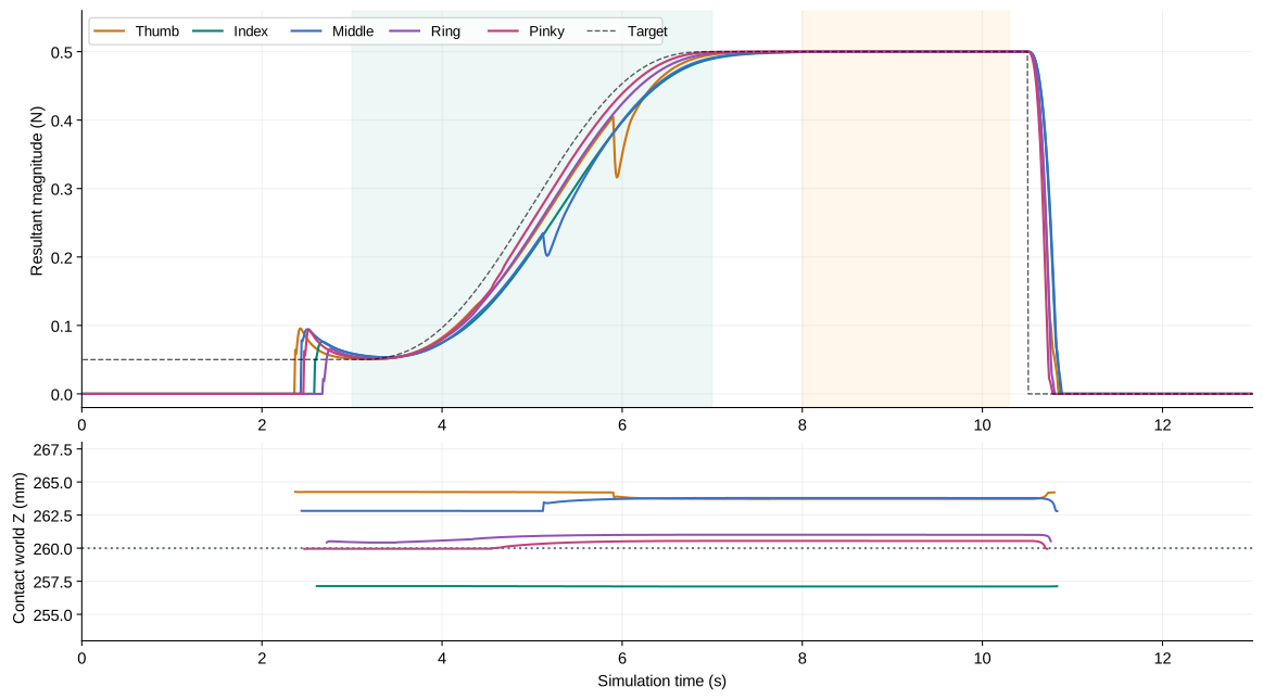
| Hold-period metric | Source-reported value |
|---|---|
| Simultaneous contacts | 5 / 5 |
| Maximum error against 0.5 N target | 0.000615 N |
| Maximum pad-center height difference | 5.80 mm |
The validation interval is 8–10.3 s. Contact-center height difference reached 6.70 mm; the minimum normal opposition angle between thumb and other fingers was 120.59°. These apply to one fixed-object pose, not general grasp success or hardware accuracy. A force-weighted mean contact position is distinct from a true center of pressure.
Explore recorded values
This explorer displays saved frames, without rerunning physics. Its fixed color range makes force changes comparable.
Loading recorded frames…
Color range ±0.01 N/pixel · red + / blue − · pale regions lie outside the sensor mask. Table values are pixel resultants.
3.9 What the ranges and checks establish
| Output | Shape/unit | Range meaning |
|---|---|---|
| Resultants | 5×3, N | No enforced bounds; signs retained |
| Virtual taxel forces | 176×3, N | Distributed contact forces, not physical ADC or normalized SDK values |
| Force images | 5×3×48×32, N/pixel | Colors alone saturate at ±0.01; stored data is not clipped |
| Pressing target | Per-finger ‖F‖=0.50 N | Experiment target, not sensor full scale or actuator limit |
Thumb Fx ranged approximately −0.00295…+0.14030 N; index Fx ranged −0.13559…+0.00000162 N. These observations do not establish hardware limits. See 15-axis ranges and 100 Hz CSV.
The original reports 17 checks: initial non-contact, gradual pressing, opposed contacts, release, rotation, geom-order signs, and pixel/taxel force-sum conservation. Zeroing native sensordata left force output unchanged, whereas zeroing contact constraint forces removed it, checking path independence. Pressing validation.
What remains to match hardware?
The pipeline connects formats and produces physically consistent forces. Hardware agreement remains a separate task. Replace assumptions with measurements in this order:
- Fix the contract. Record real info and frames together. Establish units, full scale, indices, timing, and calibration; recheck after firmware changes.
calibrate_fingertip()performs zero-baseline calibration, not full force calibration. [1] - Map space. Replace synthetic points with actual positions. Map point and aggregate axes separately; distinguish curved normals from fixed pad Fz.
- Identify dynamics against forces. Compare known loads, shear displacements, and contact positions. Adjust friction, compliance, and joint gains. Matching depth does not ensure matching force.
- Identify the observation model. Move point loads to estimate σ, asymmetry, and cross-axis coupling. Measure increasing/decreasing loads for hysteresis, thermal drift, noise, filters, delay, and saturation.
- Validate separately. Use shapes and loads excluded from calibration to evaluate resultant and contact-position errors, delay, and saturation rate. Compare physical aggregates and simulated 15 components in the same units and frames.
Hardware-like normalization requires full-scale FFS. Normal output could be clip(Fn/Fn_FS, 0, 1) and tangential output clip(Ft/Ft_FS, −1, 1), conditional on calibrated and aligned axes. Retain N separately to track saturation losses. This observation layer is not implemented.
Domain randomization can address remaining measured uncertainty, not hide frame/unit errors behind arbitrary noise. Reference [15] is visual-transfer background, not validation of this Wuji model.
These values are forces from MuJoCo 4.0’s contact solution expressed through an assumed pad region and spatial response. Following the hardware contract does not establish equality with hardware measurements.
References and evidence
The source’s external-reference check date is November 11, 2026. Core public MuJoCo APIs and the Wuji tactile contract were rechecked during blog preparation. MuJoCo links are pinned to 4.0.0; Wuji latest documentation and SDK main may change, so device metadata takes precedence. No external product photographs or paper figures were used.
- Wuji Docs — Wuji Hand 2 Fingertip Tactile. Configuration, metadata, units, frames, API, and zero-baseline calibration.
- Wuji Docs — Product Introduction, 2.2 Beta. Hand structure and rigid-model scope.
- Wuji SDK — 3.fingertip_typed.py. Field decoding, units, point/aggregate transforms; analyzed without republishing code.
- Wuji Docs — Fingertip Tactile in practice. Version-dependent units/capabilities. Some examples use old API names; [1] takes precedence.
- Wuji SDK releases. Normalization from firmware v2.4.0 and API deprecations.
- Wuji robot description. 2.1/2.2 models, pads, MIT license. Local reference commit
5c4dfa16917355d073e2e1d7e3d03897b6cf9508. - MuJoCo 4.0.0 — XML reference: tactile. Native outputs and opposing-mesh SDF requirements.
- MuJoCo 4.0.0 — engine_sensor.c. Taxels, opponents, history, scheduling. Local source comparison commit
a937a4f916dc586660145973b015e56e04043377. - MuJoCo 4.0.0 — Computation. Contact, friction, constraints; the equation here is conceptual.
- MuJoCo 4.0.0 — API functions.
mj_contactForce,mj_step,mj_forward. - MuJoCo 4.0.0 — mjContact. Position, distance, basis, ordering. The source also reports local sign checks.
- MuJoCo 4.0.0 — Modeling: Sensors. interval, nsample, delay.
- MuJoCo 3.3.5 — tactile, for comparison. Earlier penetration-pressure description, distinct from 4.0 depth.
- E. Todorov, T. Erez, Y. Tassa. MuJoCo: A physics engine for model-based control, IROS 2012. Engine background; 4.0 tactile API follows [7–12].
- J. Tobin et al. Domain Randomization for Transferring Deep Neural Networks from Simulation to the Real World, IROS 2017. Visual sim-to-real background.
- S. Wang, M. Lambeta, P.-W. Chou, R. Calandra. TACTO: A Fast, Flexible, and Open-source Simulator for High-Resolution Vision-based Tactile Sensors, IEEE RA-L 7(2), 3930–3937, 2022. DOI: 10.1109/LRA.2022.3146945. Optical tactile background; this implementation does not generate TACTO or GelSight imagery.
Implementation and results reviewed in the source
| File | Reviewed role |
|---|---|
README.md / build.py | Model sources, point layout, preserved mass/collision |
tactile_force.py | Contact selection, signs, frames, 15-axis output |
force_image.py | Spatial weighting, point/pixel distribution, conservation |
surface_contact.py | Curved grids and native SDF plate test |
foo_touch.py | Fixed object, opposed torso contact, gradual pressing |
foo_touch_viewer.py | Reading rate, data/video recording, validation |
Hashes and provenance · Force/height time series. These materials contain documentation, visuals, and result data, not full simulator source.
Visual sources and asset notice
According to the source, diagrams and plots were created for the document or generated from saved data. Videos and pad images are local MuJoCo renders. Wuji geometry uses Wuji Technology’s MIT assets; the original license is included. The source records the owner’s external-use permission for Foo Dog; its original model files are not redistributed. Original recordings retain Korean overlays, with stages, units, and legends explained in English captions above.